I2C HDMI Hacks
Hijack HDMI’s hidden DDC/CI I²C bus to automate input switching from Python on a Raspberry Pi—no remote required.
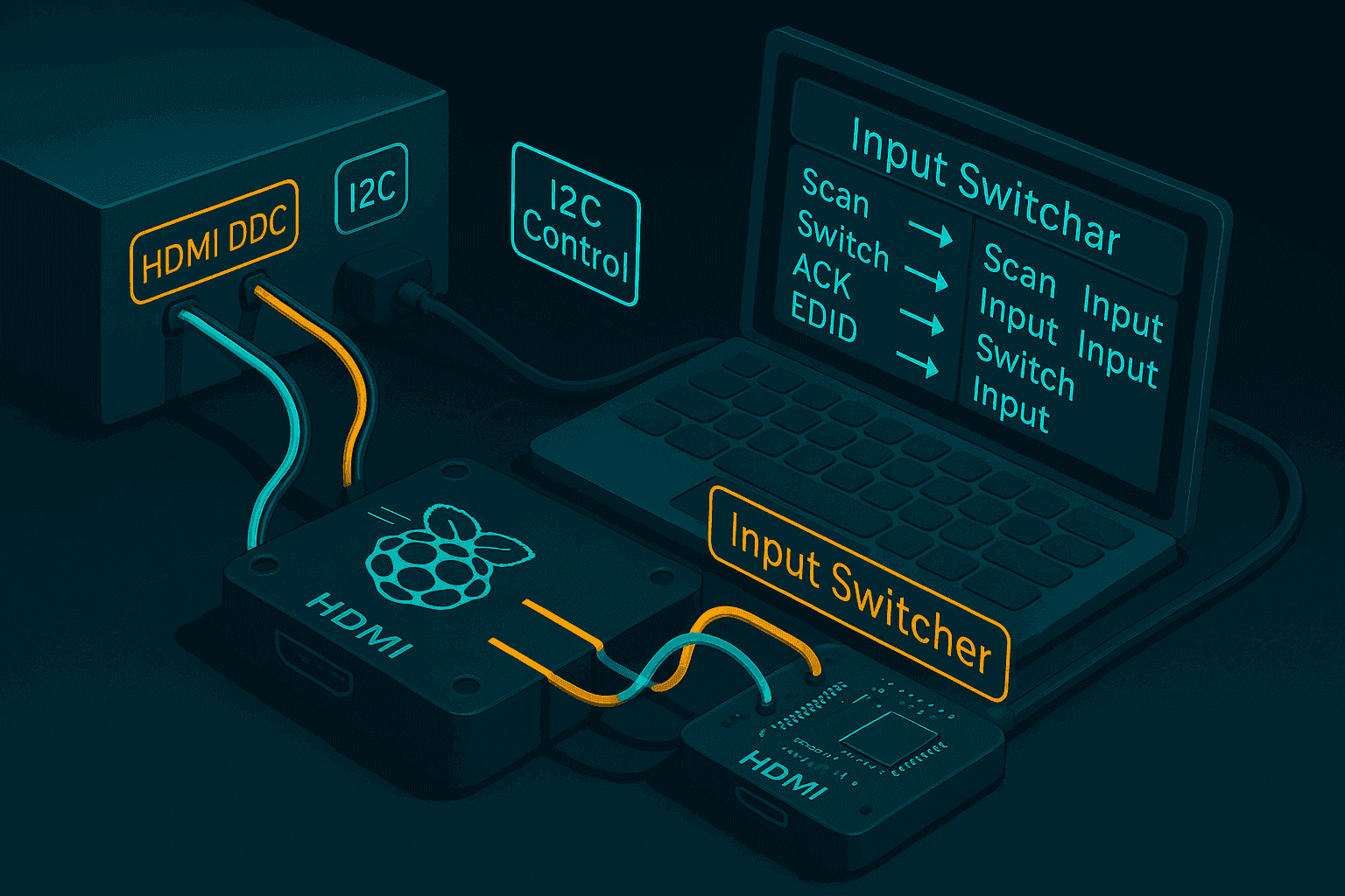
Most people think of HDMI as just a video and audio interface, but it also includes a little-known I2C bus (the DDC/CEC channel). By tapping into this interface, you can control HDMI devices in unexpected ways. In this guide, we'll explore how to use Python and I2C to switch HDMI inputs programmatically—turning your Raspberry Pi or Linux device into a powerful remote control for your AV setup.
This post will walk through the basics of HDMI I2C, hardware considerations, and Python code to automate input switching.
Overview: HDMI and I2C
- What is the DDC/CEC channel?
- Why HDMI includes I2C
- Practical uses for hackers and tinkerers
HDMI Pinout and I2C Interface
The HDMI connector contains 19 pins, with pins 15 (SCL) and 16 (SDA) carrying the I2C signals we're interested in. These pins form what's known as the DDC (Display Data Channel) bus.
Pin 15: SCL (DDC)
I2C Clock line for DDC - what we use for hacking
Hacking Potential
This I2C pin can be accessed to interact with the display's EDID and control functions, allowing us to programmatically control HDMI devices.
Pin Categories
- Video
- Ground
- Clock
- Control
- Reserved
- I2c
- Power
The highlighted pins are what we'll be tapping into for our I2C communication. The SCL pin (15) carries the clock signal, while the SDA pin (16) carries the bidirectional data. These pins normally allow the display to communicate its capabilities (like supported resolutions) to the source device, but we can hijack this channel for our own purposes.
Hardware Setup
- Required cables/adapters
- Raspberry Pi
- HDMI Monitor (that supports DDC/CI)
Finding the I2C Address on Raspberry Pi
Once your Raspberry Pi is physically connected to the HDMI DDC lines (pins 15/16), you can use the built-in I2C tools to discover which addresses are present on the bus. The i2cdetect utility is perfect for this job.
First, list the available I2C buses:
$ i2cdetect -l
i2c-2   i2c             bcm2835 (i2c@7e805000)                  I2C adapter
Here, i2c-2 is the bus connected to the HDMI port on the Pi. Now scan the bus for devices:
$ sudo i2cdetect -y 2 0 1 2 3 4 5 6 7 8 9 a b c d e f00: -- -- -- -- -- -- -- --10: -- -- -- -- -- -- -- -- -- -- -- -- -- -- -- --20: -- -- -- -- -- -- -- -- -- -- -- -- -- -- -- --30: -- -- -- -- -- -- -- 37 -- -- 3a -- -- -- -- --40: -- -- -- -- -- -- -- -- -- -- 4a 4b -- -- -- --50: 50 -- -- -- 54 -- -- -- -- -- -- -- -- -- -- --60: -- -- -- -- -- -- -- -- -- -- -- -- -- -- -- --70: -- -- -- -- -- -- -- --
This output shows several addresses in use. Most notably:
- 0x37: This is a common address for HDMI CEC (Consumer Electronics Control) bridges and sometimes for HDMI switches or other control ICs. If you're hacking input switching, this is often the chip you'll want to communicate with!
- 0x50: This is the standard EDID EEPROM address, where the monitor stores its capabilities. Reading from here gives you the display's supported resolutions and features.
- Other addresses: Depending on your monitor or switch, you may see other devices. Addresses like 0x3A, 0x4A, 0x4B, and 0x54 could correspond to additional control chips or features.
Tip: If you're not sure which address to poke, start with 0x37 for control and 0x50 for EDID. Use
i2cdumpor custom Python scripts to probe further!
Python Implementation
Now that we've identified the I2C addresses on our monitor, we can write Python code to programmatically switch inputs. Here's a minimalist implementation that works reliably:
#!/usr/bin/env python3
import os, fcntl, sys, time

BUS_DEV   = "/dev/i2c-2"    # Your I2C bus device
MON_ADDR  = 0x37           # Monitor's DDC/CI address
VCP_CODE  = 0x60           # Input Source VCP code
NEW_INPUT = int(sys.argv[1], 0) if len(sys.argv)>1 else 0x12  # Default: HDMI-2
I2C_SLAVE = 0x0703         # from <linux/i2c-dev.h>

def build_packet(vcp, value):
    pkt = bytearray([0x51, 0x84, 0x03, vcp, 0x00, value])
    pkt.append((-sum(pkt)) & 0xFF)
    return pkt

def switch_input(value):
    pkt = build_packet(VCP_CODE, value)
    print("Raw packet:", [hex(b) for b in pkt])
    fd = os.open(BUS_DEV, os.O_RDWR)
    try:
        fcntl.ioctl(fd, I2C_SLAVE, MON_ADDR)
        os.write(fd, pkt)
    finally:
        os.close(fd)

if __name__=="__main__":
    if os.geteuid()!=0:
        print("Run as root"); sys.exit(1)
    print(f"Switching to 0x{NEW_INPUT:02X}…")
    switch_input(NEW_INPUT)
    if NEW_INPUT==0x12:
        time.sleep(15)
        switch_input(0x11)
        print("Switched back to 0x11")
Here's how it works in action:
$ sudo python switch_input.py 0x12
Switching to 0x12…
Raw packet: ['0x51', '0x84', '0x3', '0x60', '0x0', '0x12', '0xb6']
Raw packet: ['0x51', '0x84', '0x3', '0x60', '0x0', '0x11', '0xb7']
Switched back to 0x11
This works perfectly! At least for me. Meaning, there verywell could be issues.
- Make sure you ran it as root.
- Make sure you are using the right i2c address.
Understanding the DDC/CI Packet Structure
Let's break down exactly what our code is sending over the I2C bus. Each byte in the packet has a specific purpose in the DDC/CI protocol:
1st Packet Breakdown:
- 0x51: Source Address - Indicates message is coming from the host device (PC) to the display
- 0x84: Packet Type - Indicates this is a message with a dedicated length byte
- 0x03: Data Length - There are 3 data bytes following this byte
- 0x60: VCP Feature Code - Code for 'Input Source Selection' according to the MCCS specification
- 0x00: MSB - Most significant byte of the 16-bit value (zero in this case)
- 0x12: LSB - Least significant byte of the 16-bit value (0x12 = HDMI-2)
- 0xB6: Checksum - Two's complement of the sum of all previous bytes
When switching back to HDMI-1, only the input value changes to 0x11, which updates the checksum to 0xB7:
Second Packet: Same structure with only two bytes changed:
- 0x11: LSB - The input source value for HDMI-1 (changed from 0x12)
- 0xB7: Checksum - Updated for the new packet values
The checksum is calculated as the two's complement of the sum of all previous bytes:
def calculate_checksum(packet_bytes):
    # Sum all bytes
    byte_sum = sum(packet_bytes)
    # Take two's complement (negate and add 1), then take lowest byte
    checksum = (-byte_sum) & 0xFF
    return checksum

# For HDMI-2 packet
packet = [0x51, 0x84, 0x03, 0x60, 0x00, 0x12]
checksum = calculate_checksum(packet)  # Returns 0xB6

# For HDMI-1 packet
packet = [0x51, 0x84, 0x03, 0x60, 0x00, 0x11]
checksum = calculate_checksum(packet)  # Returns 0xB7
Understanding this packet structure allows you to send commands to any monitor supporting the DDC/CI standard.
Understanding Input Source Codes
We know to use 0x11 (HDMI-1) and 0x12 (HDMI-2) based on the MCCS (Monitor Control Command Set) specification, specifically the definition of VCP feature code 0x60, which controls the "Input Source" of the monitor.
Official Input Source Values (VCP Code 0x60)
According to the VESA MCCS 2.2 spec — page 57+ — the standard values for input sources are:
| Value | Input Source |
|---|---|
| 0x01 | VGA-1 |
| 0x03 | DVI-1 |
| 0x04 | DVI-2 |
| 0x0F | DisplayPort-1 |
| 0x10 | DisplayPort-2 |
| 0x11 | HDMI-1 |
| 0x12 | HDMI-2 |
| 0x1C | USB-C |
| 0x1E | Wireless Display |
Discovering Your Monitor's Values
You can query your monitor to see what input source codes it supports:
sudo ddcutil getvcp 0x60
It will return something like:
VCP code 0x60 (Input Source):
  current value = 0x11, max value = 0x12
This confirms that:
- 0x11 is HDMI-1 (currently selected)
- 0x12 is HDMI-2 (supported)
If your monitor had DisplayPort or DVI inputs, you'd likely see those too.
Conclusion
Unlocking the I2C channel on HDMI opens up a world of possibilities for automation and control. With just a bit of hardware and some Python, you can take command of your devices in ways manufacturers never intended. What we are doing with it is just to change HDMI inputs. This project was all to help me understand how I can Control my custom pc case's front facing LCD. I also wanted to see if I could make a simple tool to switch HDMI inputs. This scripts is a good starting point for anyone that might want to hack on DDC and I2C on monitors directly from Python.
Related Resources
- ddcutil:
- DDCI: